Product Summary
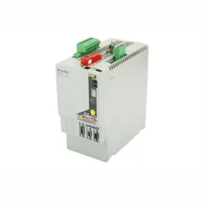
The GE IS200TRPGH1BCC Primary Trip Terminal Board manages critical safety functions for gas turbines. This board integrates nine magnetic relays across three voting circuits. It also accepts inputs from eight Geiger-Mueller flame detectors. Engineers rely on this board for reliable trip solenoid control. It works seamlessly with both Mark VI and Mark VIe systems.
Theme A: Product Procurement & Buyer Guide
Procurement managers must verify the IS200TRPGH1BCC supports TMR applications. This board uses three voting relays per trip solenoid. This design provides triple modular redundancy for maximum safety. The board operates with a 125 V dc solenoid voltage. It also requires a 28 V control relay coil supply. The flame detector supply operates at 335 V dc. These specifications ensure compatibility with existing gas turbine systems.

This terminal board interfaces directly with the VTUR board in Mark VI systems. It connects to the VME rack through cables with molded plugs. For Mark VIe systems, the PTUR packs on TTURH1C control this board. The D-type connectors on TTURH1C accept the I/O packs as input. This flexibility simplifies integration into both simplex and TMR architectures. Engineers can confidently specify this board for new or upgrade projects.
The board features two large terminal blocks with 48 total terminals. This layout simplifies wiring and reduces installation errors. The board also includes three connector ports with 37 female ports each. These ports ensure secure and reliable connections to other system components. The board's robust construction includes various capacitors for signal filtering. This design guarantees stable operation in demanding industrial environments.
Theme B: Step-by-Step User & Installation Guide
Begin by mounting the IS200TRPGH1BCC securely in the VME rack. Ensure the rack provides adequate ventilation for the board. Connect the VTUR board using cables with molded plugs. Verify the cable connections are tight and secure. This step prevents intermittent faults during operation.

Wire the three trip solenoids to the appropriate terminal block positions. The board supports solenoids with a 125 V dc rating. The solenoid response time features a 0.1 sec L/R time constant. Current suppression uses a metal oxide varistor for protection. Connect the 28 V control relay coil supply to the designated terminals.
Connect the eight Geiger-Mueller flame detectors to the board inputs. The flame detector supply requires 335 V dc. Verify each detector connection is correct for proper flame sensing. The board processes these signals to determine turbine flame status. This information is critical for safe turbine startup and shutdown.
Finally, configure the voting circuits for TMR or simplex operation. The H1B version supports TMR with three voting relays per solenoid. This configuration provides the highest level of fault tolerance. Test all connections before powering the system. Verify the trip solenoids respond correctly to test signals.

Logistics & Standard Packaging Details
- One GE IS200TRPGH1BCC Primary Trip Terminal Board
- Anti-static packaging for safe transport and handling
- Product documentation and reference manual GEH-6421J
- Express delivery shipping available via FedEx, UPS, and DHL