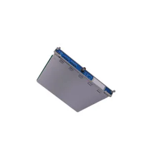
Product Summary
The Allen-Bradley 1794-ACNR is a dedicated Flex I/O communication adapter. This module supports redundant ControlNet highways for maximum system uptime. It reliably bridges Flex I/O modules with a control network. This 1794-ACNR unit handles data exchange at a robust 5 Mbps speed.
Product Procurement & Buyer Guide: Securing Your High-Availability Network
Evaluating Redundancy for Critical Processes
The 1794-ACNR delivers a true redundant ControlNet media adapter solution. It features two distinct ControlNet BNC ports. Each port connects to a separate trunk cable. This dual-path design ensures zero data loss during a single trunk failure. For mission-critical production lines, this redundancy is non-negotiable. It eliminates a single point of network failure.

Technical Alignment with Your System
Check your system voltage before purchase. This module requires an external 24V DC supply. It accepts a wide input range from 19.2 to 31.2 Volts DC. The maximum power dissipation is just 4.6 Watts. This efficiency keeps your control cabinet cool. You can mount up to eight Flex I/O modules along this adapter. This flexibility supports mixed analog and discrete I/O configurations.
Robust Environmental Specifications
This module operates reliably in harsh factory environments. Its operating shock rating is 30 g per IEC 60068-2-27. It withstands vibration of 5 g at 10 to 500 Hertz. The unit functions in temperatures from -20 to 55 degrees Celsius. These specs make the 1794-ACNR ideal for demanding applications. It handles the thermal stress of enclosed cabinets effectively.
Step-by-Step Installation Guide for the 1794-ACNR Adapter

Proper Mechanical Mounting
The 1794-ACNR utilizes a standard DIN rail mounting system. First, securely attach an appropriate DIN rail inside your enclosure. Then, clip the adapter onto the rail firmly. This module uses an open-type enclosure for heat dissipation. Therefore, you must place it within a proper protective cabinet. The unit measures just 3.7 x 3.6 x 3.4 inches.
Electrical and Network Connections
Connect your 24V DC power to the designated terminals. The unit draws a maximum of 400 mA from the supply. Use a ControlNet cable of 12 AWG maximum. Connect the first trunk to the Comm A BNC port. Connect the second trunk to the Comm B BNC port. Each port supports the full 5 Mbps data transfer speed.

Verifying Operational Status
After powering on, check the LED indicators for correct operation. The I/O status LED will show green upon a successful connection. Comm A and Comm B LEDs show network status. A steady green light indicates a good connection. Red lights signal a network fault or cabling issue. This visual system simplifies initial troubleshooting.